Principle and failure analysis of high-voltage interlock for new energy vehicles
The high-voltage interlock design is used as a monitoring method for the high-voltage system of electric vehicles in the design of automotive circuits. During the working process of the high-voltage system of electric vehicles, the biggest risk is that the vehicle suddenly loses power and loses power. There are many reasons for the loss of vehicle power, one of which is the loose connection of the high voltage circuit. The high-voltage interlock design can monitor the continuity of the circuit, and send an alarm signal to the VCU before the high-voltage power failure, so that the VCU can take countermeasures for the entire vehicle system.
Another type of risk point of electric vehicles is human misoperation during system operation and manual disconnection of high-voltage connectors. At the moment of disconnection, the entire loop voltage is applied to both ends of the connector terminals, and the high-voltage connector itself does not have the breaking capacity. The voltage breaks down the air and produces a strong arc between the two devices, which may affect the surrounding parts of the breakpoint. Injury to persons and equipment. The existence of the high-voltage interlock design can disconnect the output of the power battery at the same time when the connector is disconnected to avoid electric shock.
1.1 Definition of high voltage interlock
High Voltage Inter-lock (HVIL for short) is a safety design method that uses low-voltage signals to monitor the integrity and continuity of high-voltage circuits. The high-voltage interlock design can identify abnormal disconnection or damage of the high-voltage circuit, and disconnect the high-voltage power in time. Theoretically, the low-voltage monitoring circuit is disconnected before the high-voltage, and then connected, and the necessary advance is maintained in the middle. The length of time can be determined according to the specific strategy of the model.
1.2 High voltage interlock principle
All the connection positions of the high-voltage connector in the vehicle need a high-voltage interlock signal circuit, but the interlock circuit and the high-voltage circuit do not have a necessary connection. The high voltage on the whole vehicle, electrical appliance A and electrical appliance B form a complete circuit. However, in the high-voltage interlock design, it is possible to set a separate interlock signal circuit for A electrical appliances, and at the same time set a separate interlock signal circuit for B electrical appliances; it is also possible to connect the interlock signals of A and B in series in one circuit. That is, the interlock circuit can be designed as a parallel mode or as a series mode.
The high-voltage system of the whole vehicle uses the power battery as the power source, and the low-voltage circuit also needs a power supply for detection, so that the low-voltage signal can be transmitted along the closed low-voltage circuit. When the low-voltage signal is interrupted, it means that a certain high-voltage connector is loose or falls off. The basic principle of high voltage interlock is shown in Figure 1/Figure 2. On the basis of the high-voltage interlock signal circuit, design a monitoring point or a monitoring circuit, which is responsible for transmitting the status of the high-voltage interlock signal circuit to the BMS.
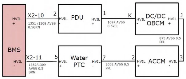
The picture above is a diagram of the electrical principle of a certain electric vehicle high-voltage interlock.
The electric vehicle adopts a series connection method. The high-voltage interlocking low-voltage detection line is drawn from the positive pole of the BMS, and then returns to the negative pole of the BMS through the PDU-DCDC-ACCM-PTC to form an interlocking circuit. In the case of normal power-on, the output voltage of the interlock circuit is generally ≥5V and ≤9V. When you need to check whether there is a high-voltage interlock problem, check the voltage of the two pins of the BMS input and output, and it is normal within the design voltage range. Or measure the loop resistance directly. In theory, the loop resistance value is 0Ω, and it can be regarded as 0Ω if it is lower than 5Ω.